DOG TOYS
How to Build a DIY Robot Dog Toy: ESP32 Parts to Setup Guide
This guide walks through soldering, assembling, and configuring an ESP32-C3-based DIY robot dog toy, while explaining why real dogs may not respond to it the way they do to a squeaky ball.
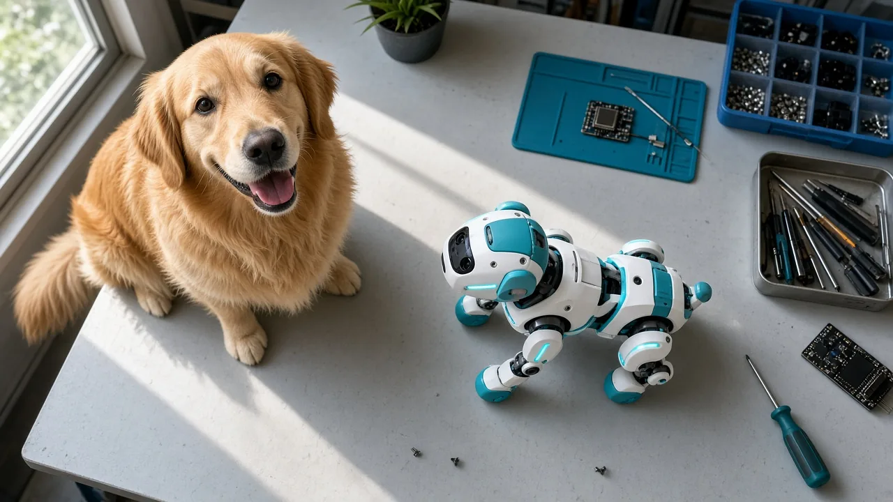
If you’re wondering how to build a DIY robot dog toy, the short answer is: you solder an ESP32-C3 board, four small servos, and a few sensor modules onto a compact frame, then connect the finished unit to WiFi before your dog ever sees it. The whole process is closer to an electronics kit than a toy purchase. Whether the result actually interests your dog is a separate question, and one worth asking before you buy a single part.
What You’ll Learn and What You Need Before You Start
This guide walks through assembling a small robot dog built around an ESP32-C3 Super Mini development board, which comes with 4MB of flash storage built in. You’ll solder several modules onto the mainboard, mount four servos for movement, wire up LED strips for lighting effects, and connect audio and touch components so the robot can respond to sound and touch.
The core parts list includes:
- ESP32-C3 Super Mini board (the brain of the robot)
- Four SG90 180-degree servos (for legs, tail, and ear movement)
- Two WS2812B LED strips
- An amplifier module with a small speaker
- A microphone module
- A touch sensor module
- A charge/discharge module, power switch, and small battery
This project suits a patient first-time maker who enjoys following a wiring diagram step by step and doesn’t mind troubleshooting a loose connection. It does not suit a dog who chews toys, since the finished unit is a hard-shelled electronic device, not a chew toy. Think of this as a build-it project for a person first, and a dog’s entertainment second.
How to Build a DIY Robot Dog Toy: Soldering the Electronics
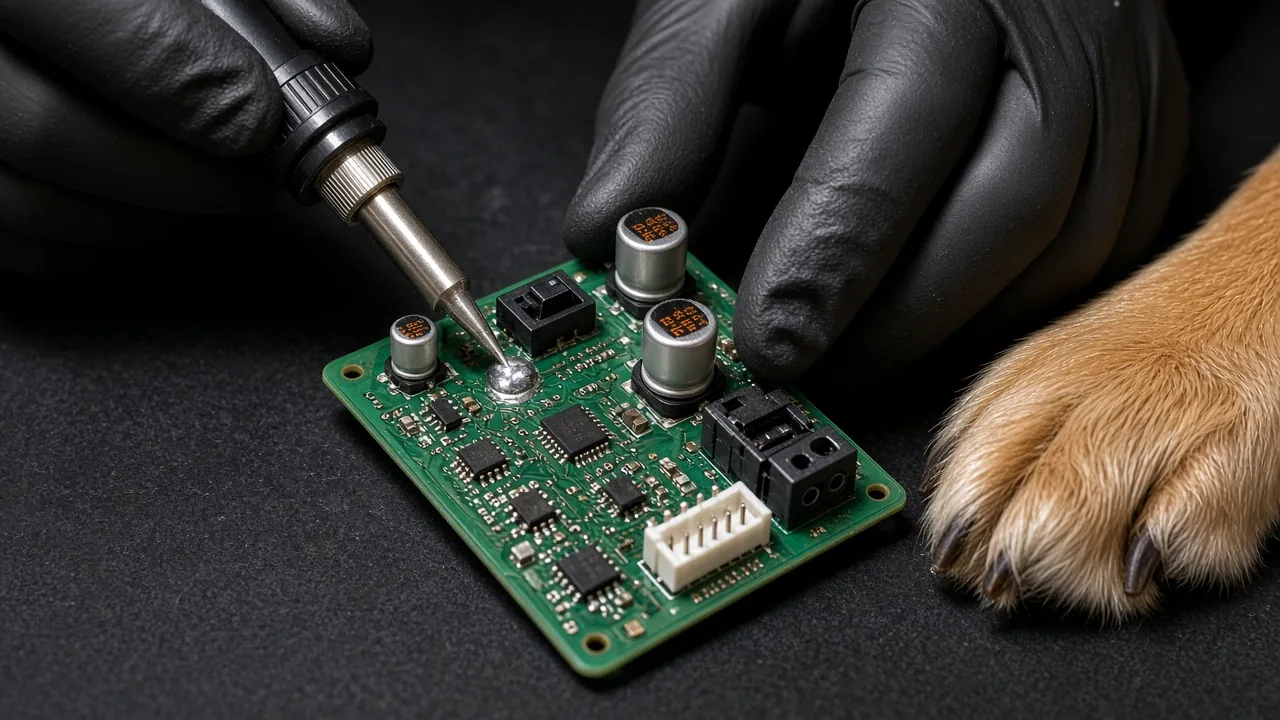
The soldering stage is where most build problems start, and where a little patience up front saves you from reopening the enclosure later. You’ll be working with the charge/discharge module, a power switch, two 220μF electrolytic capacitors, a PH2.0 2-pin battery socket, headers for the leg servos, and a few small connectors for the screen and touch module.
A reliable order makes the job easier:
- Tack down one pad on each part (switch, battery socket) before soldering the rest of its pins. This keeps parts from shifting or falling off mid-solder.
- Mount the two 220μF capacitors, matching the long lead (positive) to the pad marked with a positive symbol. Insert fully, solder, then trim the extra lead length with a nail clipper so it doesn’t short against anything nearby.
- Attach the amplifier module and small speaker.
- Solder the microphone module with its longer header pins facing up. If you solder it the other way, those pins can poke into the ESP32 core board once the layers stack together.
- Install the touch module, but first remove the small resistor on it labeled for self-latching. Without removing this resistor, the touch sensor won’t register as a quick tap (momentary mode); it will behave more like a toggle switch instead.
Each of these steps addresses a specific failure that build commenters reported after reassembly, from capacitors installed backward to touch sensors that wouldn’t respond correctly. Catching them during soldering is far easier than diagnosing them after the case is closed.
Why Wiring by Label, Not Wire Color, Prevents Common Mistakes
One of the most common points of confusion in this build is matching wires between the touch module and the mainboard. Builders have pointed out that the touch module’s power pin reads as V, while the connecting cable’s wire color doesn’t obviously match that label, leading some to wire V to the wrong pin entirely.
The judgment rule that solves this: always match the printed letter markings on each module’s header, not the color of the wire connecting them. Look for V (power), G (ground), and I (data/input) printed directly on the board silkscreen, and connect pin to pin based on those letters. This same rule applies to the WS2812B LED strips later in the build, where V goes to 5V, G to ground, and I or DIN to the data line.
Wire colors can vary between cable batches, but the printed labels on the module itself don’t change. If something doesn’t light up or respond after assembly, re-checking label-to-label connections is the first thing to look at before assuming a part is defective.
How to Test the Board Before Full Assembly
Before mounting anything into the body, plug in the battery and test the speaker and microphone while everything is still accessible. This single step catches a loose solder joint before it’s buried under servos and screws, which is far harder to fix once the enclosure is sealed.
If the speaker or microphone doesn’t respond:
- Suspect a loose connection first, not a failed solder joint. Gently flex or wiggle the board near the suspect connector and retest.
- Reheat and reflow any pad that looks dull or has a visible gap rather than a smooth solder dome.
- Only after ruling out a loose connection should you consider that a component itself may be faulty.
Testing early also means you’re not disassembling a fully built robot to chase down a wiring issue later, which is one of the more frustrating experiences builders have reported with this project.
How to Assemble the Body, Servos, and Legs
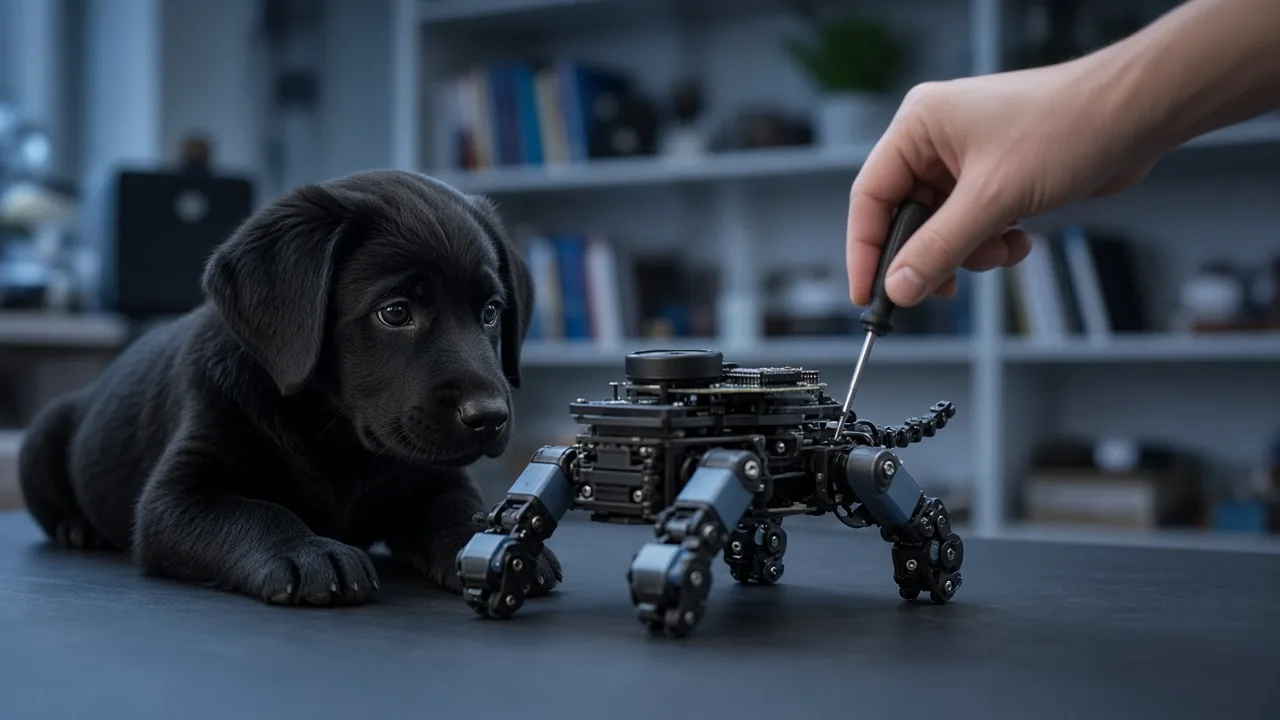
Once the electronics test out, assembly follows a logical order that keeps smaller, harder-to-reach parts accessible early and bigger structural pieces for last.
A dependable sequence looks like this:
- Speaker and touch module – Attach both using double-sided tape in their designated spots.
- Mainboard – Align it to the molded guide notches in the case and secure it with M2×6 screws.
- LED strips – Feed the WS2812B strips into their mounting slots and tidy the wiring so nothing is pinched.
- Screen – Peel the protective film off the display before snapping on its cover plate.
- Four servos – Mount each one with its base oriented so the single mounting hole faces forward; this is how you tell left from right during installation.
- Servo arms (legs, tail, ears) – Position the arm as high as it will go before locking it onto the servo spline.
- Legs with non-slip pads, tail, and ears – Finish with these decorative and stabilizing pieces.
The arm position in step 6 matters more than it looks. Once the robot is assembled, you can only fine-tune servo angles by moving them further upward through software, not by physically repositioning the arm. If you mount a leg or ear arm too low to begin with, you may hit the servo’s upper adjustment limit before the pose looks right, and have no way to correct it short of reopening the joint.
While wiring the servos and LEDs, route the longer servo cables toward the front of the body where there’s more open space, and keep wiring away from the rear section where the ESP32’s antenna sits. Cables resting across the antenna area can interfere with WiFi reception once you get to the setup stage.
How to Flash the Firmware to the ESP32 Board
With the body assembled, the next step is loading the firmware onto the ESP32-C3 so it actually runs the robot’s behaviors. This requires putting the board into download mode, which uses a specific button sequence:
- Press and hold the left button on the board.
- While still holding the left button, press the right button.
- Release the right button first, then release the left button.
This sequence puts the board into a state where your computer’s flashing software can write new firmware to it. In that software, select ESP32C3 as the chip type, and enter "0" in the address field before choosing the correct COM port and starting the flash.
Skipping or reordering any part of this button sequence is one of the most common reasons a flash attempt fails. If the flashing software doesn’t detect the board or the process stalls partway through, redo the button sequence exactly as described before troubleshooting anything else, including cables or drivers.
How to Set Up WiFi and Finish First-Time Configuration
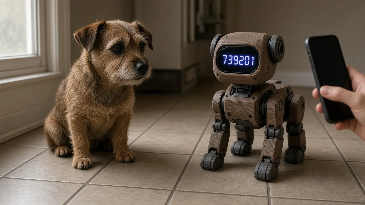
Getting the robot online is a two-step process, and both steps need to be completed before any AI chat or voice features will work.
Step one: connect to the robot’s hotspot. On your phone, join the WiFi network broadcast by the robot (it will appear with a name starting with the device’s assigned prefix). From there, you’ll enter your home WiFi credentials so the robot can connect to your actual network.
Step two: verify the device online. Once connected to your home network, the robot’s screen will display a six-digit verification code. Log into the companion configuration website and enter that code to complete device authentication.
Until both steps are finished, the robot may power on and move, but features that depend on an internet connection, including any AI conversation function, simply won’t activate. If you’ve completed the hotspot step but skipped the verification code login (or vice versa), that’s the first thing to check before assuming something is broken.
How to Fine-Tune Servo Angles and Add Extra Features
After setup, you can access a control console by scanning a QR code and holding down the touch sensor on the robot. This lets you adjust individual servo angles for things like ear position, tail angle, and leg pose.
Builders recommend making these adjustments while the robot is in its "sleep" pose, since the resting position makes small angle changes easier to see and compare. Remember to save any adjustment once you’re satisfied, since unsaved changes won’t persist after a restart.
Beyond basic movement, some builders expand the robot’s abilities by connecting it to a third-party music API, letting it play audio on command. This is a reasonable add-on if you’re comfortable working with APIs, but it does add another layer of setup and troubleshooting on top of an already involved build. For a first attempt, it’s worth getting the base robot working reliably before adding music playback or other extras.
Is a DIY Robot Dog Toy Actually Safe and Fun for Your Dog
Here’s where it’s worth stepping back. Building a convincing robot dog is a maker’s goal: Does it move smoothly? Does it respond to touch? Does it look lifelike? None of that is the same question as whether your dog will actually want to interact with it.
For a sense of what does reliably grab a dog’s attention, consider one dachshund’s well-documented favorite toy: a simple squeaky ball. The appeal has nothing to do with technology and everything to do with instinct. The dog treats the ball like prey, carrying it around, hiding it in couch cushions or bags, and tearing off the attached tag as part of the fun. He also has a clear color preference for blue, for reasons his owner admits remain a mystery.
That contrast matters if you’re deciding whether to invest a weekend in a DIY robot build. A soldered circuit board and plastic shell, however well executed, doesn’t squeak, doesn’t compress under a bite, and doesn’t trigger a dog’s hunting instinct the way a soft, noisy toy does. If your dog’s play style centers on carrying, shaking, or "catching" something, a robot dog toy is unlikely to compete with a $5 squeaky ball for his attention.
Why Real Dogs May Respond Differently to a DIY Robot Than to Chew Toys
It’s worth repeating directly: this build is not meant to be chewed, mouthed, or carried around like a plush toy. The enclosure is a hard plastic shell housing circuit boards, a battery, and small screws, none of which are designed to survive dog teeth or stand in for a squeaky ball a dog can grip and shake.
If your dog is the type to immediately pick up anything new and start chewing, this project isn’t a toy for him at all, no matter how well you build it. It’s closer to a smart home gadget shaped like a dog, intended to be watched and interacted with gently, kept out of reach of jaws, paws, and curious noses when unsupervised.
Common Problems When Building a DIY Robot Dog Toy
Several concerns come up again and again among people attempting this build, and they’re worth addressing honestly rather than glossing over.
Battery capacity for four servos. Some builders have raised a real technical concern: can a small battery reliably power four servos at once without the sudden current draw causing the board to reset or brown out? This is a legitimate risk with small-battery robotics projects generally, and if you notice the ESP32 restarting or behaving erratically when multiple servos move at once, battery capacity or wiring resistance is a reasonable place to start investigating.
Unclear wiring diagrams. The V/G/I labeling confusion around the touch module isn’t an isolated case; several builders have found the diagram’s visual layout easy to misread, even when the printed labels are correct. If a diagram and your intuition disagree, trust the printed labels on the actual module over any mental shortcut about "left pin always being ground."
Parts sourcing. A recurring frustration is not knowing exactly where to source every individual part, or whether a complete kit exists. Some builders have asked for a single consolidated parts list or kit option specifically to avoid buying the wrong component and getting stuck mid-build.
Enclosure design availability. Whether the 3D-printable case files are openly shared, or whether you need to source the shell separately, is a common question without a universal answer; availability can vary and may require checking current project resources directly rather than assuming the files are included with instructions.
Other frequent questions include whether IO pins are already fully used (limiting room for extra sensors like a DHT11 temperature/humidity module) and whether swapping servo-driven legs for simpler mechanical linkages would meaningfully cut cost. Both are reasonable considerations if you’re planning modifications, but they add complexity beyond a first build.
Troubleshooting: Fixing Common DIY Robot Dog Toy Issues
These are general checks, not guaranteed fixes, since every build has its own quirks depending on soldering quality and parts batch.
No sound from the speaker or microphone:
- Reflow the solder joint on the amplifier and speaker connections; a dull or incomplete joint is the most common cause.
- Confirm the microphone’s long header pins are oriented correctly and not pressed against the ESP32 board, which can cause intermittent shorts.
- Retest with the case open before reassembling, since a connection that works loose can look fine until the parts are compressed into the shell.
WiFi pairing fails:
- Confirm you completed both configuration steps: joining the robot’s hotspot and entering your home network’s credentials, then separately logging in with the six-digit verification code.
- Double-check you’re entering the code shown on the robot’s screen at that exact moment, since codes may be time-sensitive.
- If the hotspot never appears on your phone, recheck the firmware flash completed successfully rather than assuming a WiFi hardware fault.
Servo angle stuck at its adjustment limit:
- This usually traces back to how the arm was mounted during assembly. If the arm was installed too low on the servo spline, you can only adjust upward from there, and may hit the mechanical limit before reaching the pose you want.
- Unfortunately, the fix is often reopening that joint and remounting the arm higher on the spline, since software adjustment alone can’t move past the servo’s physical range.
Frequently Asked Questions
Can the robot be controlled by voice commands for specific movements?
Voice-based movement control isn’t a standard documented feature of this build; most movement adjustment happens through the touch-and-console method after setup.
Where can I find the firmware or 3D model files?
Availability of model files and firmware updates can vary by project and may require checking current community resources directly, since this isn’t something guaranteed to be bundled with every version of the build.
Does the robot support general AI chat functionality?
Yes, but only once both WiFi configuration steps are fully completed. If either the hotspot connection or the verification code login is skipped, chat features won’t activate even if the robot powers on normally.
Can I add sensors like a DHT11 temperature and humidity module?
It depends on how many IO pins are already committed to existing components. Some builders have found available pins limited after wiring servos, LEDs, audio, and touch modules, so check your specific board’s remaining IO before planning an addition.
Building a DIY robot dog toy is a genuinely interesting electronics project, but it’s worth matching your expectations to what it actually delivers: a programmable, movable device you built yourself, not necessarily something your dog will treat as a toy. Before investing a weekend of soldering and setup, think honestly about how your dog actually plays, whether that’s chewing, chasing, carrying, or digging, and choose accordingly. And whatever toy ends up in your dog’s rotation, DIY or off the shelf, check it regularly for loose parts, worn seams, or exposed components, and retire anything that’s starting to show damage.
This article is for general information only and is not a substitute for advice from your veterinarian. Always supervise your pet with a new toy, and replace any toy that is damaged or small enough to swallow.

Contributor
admin
Continue reading
All stories
DOG TOYS · 11 October
How to Clean Smelly Plush Dog Toys Safely at Home

DOG TOYS · 11 October
Is Tether Tug Durable for Strong Dogs? What Owners Report

DOG TOYS · 11 October
Responses
Moderated discussion